Introduction: Why Stainless Steel Hose Barbs with NPT Threads Are the Industry Standard
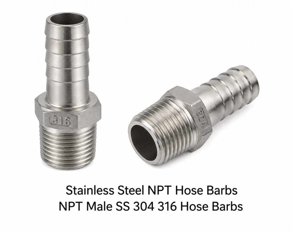
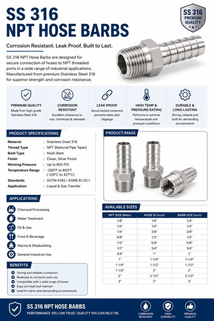
Stainless steel hose barbs with NPT (National Pipe Taper) threads are the dominant fluid-connection technology across industrial, chemical, pharmaceutical, food processing, marine, and instrumentation sectors worldwide. The NPT taper thread — governed by ASME B1.20.1 — achieves a pressure-tight mechanical seal through controlled thread interference, while the precision-machined barbed shank grips the hose bore internally to resist pull-out forces at pressure. When this proven thread form is combined with AISI 304 or AISI 316 stainless steel, the result is a fitting that simultaneously delivers corrosion immunity, hygienic cleanability, mechanical strength, and a service life measured in decades rather than years.
This technical guide covers every aspect an engineer, procurement specialist, or plant maintenance professional needs: raw material chemistry and international alloy equivalents, NPT thread geometry and dimensional standards, a step-by-step CNC manufacturing process, mechanical and pressure-rating data, installation best practices, and a comprehensive comparison against brass and plastic alternatives. It is authored for the global stainless steel fittings supply chain and is applicable to applications spanning from 1/8 inch NPT to 2 inch NPT and hose sizes from 3 mm to 50 mm.
What Is a Hose Barb Fitting? Anatomy and Functional Geometry
A hose barb fitting is a push-in connector whose external barbed profile — a series of angled ridges with a larger-diameter crown and a narrower root — creates mechanical interference with the inner bore of a flexible hose. When a hose is pushed onto the barb, the hose wall stretches over each ridge and then contracts behind it, generating a multi-point grip that resists both axial pull-out and internal pressure forces. The NPT end provides the rigid-pipe or manifold connection through tapered thread engagement.
Key Functional Zones of an NPT Hose Barb
| Zone | Description | Engineering Function |
|---|---|---|
| NPT Thread | Tapered male thread per ASME B1.20.1 at 1/16 inch per inch taper | Creates pressure-tight mechanical seal via thread interference; no additional sealant required in many applications (PTFE tape recommended for hydraulic service) |
| Hex Body / Wrench Flat | Hexagonal section between thread and barb | Provides purchase for torque wrench during installation; prevents over-insertion into port |
| Transition Cone | Chamfered entry from hex to barb shank | Guides hose onto first barb without splitting; reduces assembly force |
| Barb Profile | 1–4 annular ridges with forward taper angle 15–25° and reverse locking angle 60–90° | Forward taper eases hose installation; steep reverse angle resists pull-out; ridge count scales with hose OD |
| Shank OD | Nominally equal to or slightly larger than hose ID (typically +0.3 to +0.8 mm interference) | Provides hose retention via radial compression; correct interference is critical to leak-free performance |
| Bore (Through-Passage) | Straight or slightly tapered internal bore | Establishes flow area; smooth bore minimises turbulence and pressure drop |
Raw Material: SS 304 and SS 316 Alloy Chemistry for Hose Barb Fittings
The selection of stainless steel grade is the single most important decision in hose barb specification. SS 304 (UNS S30400) and SS 316 (UNS S31600) are both austenitic stainless steels with a face-centred cubic crystal structure that confers excellent toughness and non-magnetic properties. The key chemical difference is the addition of 2.0–3.0% molybdenum in SS 316, which dramatically improves resistance to pitting and crevice corrosion — particularly in chloride-containing media such as seawater, saline process streams, and chemical plant effluent.
Chemical Composition: SS 304 vs SS 316
| Element | SS 304 (AISI/ASTM) | SS 316 (AISI/ASTM) | Role in Alloy |
|---|---|---|---|
| Carbon (C) | 0.08% max | 0.08% max | Low carbon prevents carbide precipitation during welding; L-grade (304L/316L) reduces to 0.03% max |
| Manganese (Mn) | 2.00% max | 2.00% max | Austenite stabiliser; improves hot workability |
| Silicon (Si) | 0.75% max | 0.75% max | Deoxidiser; slightly increases oxidation resistance at elevated temperature |
| Chromium (Cr) | 18.0–20.0% | 16.0–18.0% | Primary corrosion barrier; forms passive Cr2O3 surface layer |
| Nickel (Ni) | 8.0–10.5% | 10.0–14.0% | Austenite stabiliser; enhances toughness and ductility |
| Molybdenum (Mo) | — | 2.0–3.0% | Pitting and crevice corrosion resistance; critical for chloride environments |
| Phosphorus (P) | 0.045% max | 0.045% max | Controlled as impurity; excessive P reduces toughness |
| Sulphur (S) | 0.030% max | 0.030% max | Controlled as impurity; free-machining grades (303, 416) have higher S for tool life |
| Nitrogen (N) | 0.10% max | 0.10% max | Interstitial strengthener; improves pitting resistance |
International Alloy Equivalents for SS 304 and SS 316
| Standard | SS 304 Designation | SS 316 Designation | Country/Region |
|---|---|---|---|
| AISI / ASTM (USA) | 304 / S30400 | 316 / S31600 | United States |
| EN / DIN (Europe) | 1.4301 (X5CrNi18-10) | 1.4401 (X5CrNiMo17-12-2) | European Union / Germany |
| BS (UK) | 304S31 | 316S31 | United Kingdom |
| JIS (Japan) | SUS 304 | SUS 316 | Japan |
| IS (India) | X04Cr19Ni9 / IS 6911 | X05CrNiMo17-12-2 | India |
| GB (China) | 0Cr18Ni9 / 06Cr19Ni10 | 0Cr17Ni12Mo2 / 06Cr17Ni12Mo2 | China |
| GOST (Russia) | 08Kh18N10 | 08Kh17N13M2T | Russia / CIS |
| NF (France) | Z6CN18-09 | Z6CND17-11 | France |
| UNS (USA Unified) | S30400 | S31600 | USA — unified numbering |
| SAE (USA) | SAE 30304 | SAE 30316 | USA — automotive/engineering |
Key Mechanical Properties Comparison: SS 304 vs SS 316
| Property | SS 304 | SS 316 | Test Standard |
|---|---|---|---|
| Tensile Strength (min) | 515 MPa (75 ksi) | 515 MPa (75 ksi) | ASTM A276 / A479 |
| Yield Strength (0.2% offset, min) | 205 MPa (30 ksi) | 205 MPa (30 ksi) | ASTM A276 / A479 |
| Elongation (min) | 40% | 40% | ASTM A276 / A479 |
| Hardness (Rockwell B max) | 92 HRB | 95 HRB | ASTM E18 |
| Density | 7.93 g/cm³ | 7.98 g/cm³ | — |
| Modulus of Elasticity | 193 GPa | 193 GPa | — |
| Thermal Expansion Coefficient | 17.2 × 10⁻⁶/°C | 15.9 × 10⁻⁶/°C | 0–100°C range |
| Max Service Temperature (continuous) | 870°C (oxidising) | 870°C (oxidising) | — |
NPT Thread Standard: ASME B1.20.1 Technical Specification
NPT (National Pipe Taper) threads are defined by ASME B1.20.1 — the American standard that specifies thread form, taper, pitch, tolerance, and gaging requirements for pipe threads. The taper angle of 1/16 inch per inch (1° 47′ 24″) of thread length means that as the male thread is screwed into the female thread, flank-to-flank contact increases and the threads jam against each other, creating an inherently leak-resistant joint. PTFE thread tape (or anaerobic thread sealant) fills any micro-gaps and prevents corrosion of the engaged flanks.
NPT Thread Dimensions Table (ASME B1.20.1)
| NPT Size | Nominal Pipe OD (inch) | Threads per Inch (TPI) | Pitch (inch) | Thread Height (inch) | Engagement Length (inch) | Hose ID Range (mm) |
|---|---|---|---|---|---|---|
| 1/8″ | 0.405 | 27 | 0.0370 | 0.0230 | 0.180 | 3–6 |
| 1/4″ | 0.540 | 18 | 0.0556 | 0.0350 | 0.200 | 6–10 |
| 3/8″ | 0.675 | 18 | 0.0556 | 0.0350 | 0.240 | 8–13 |
| 1/2″ | 0.840 | 14 | 0.0714 | 0.0444 | 0.320 | 10–16 |
| 3/4″ | 1.050 | 14 | 0.0714 | 0.0444 | 0.339 | 13–20 |
| 1″ | 1.315 | 11.5 | 0.0870 | 0.0539 | 0.400 | 19–25 |
| 1-1/4″ | 1.660 | 11.5 | 0.0870 | 0.0539 | 0.420 | 25–32 |
| 1-1/2″ | 1.900 | 11.5 | 0.0870 | 0.0539 | 0.420 | 32–38 |
| 2″ | 2.375 | 11.5 | 0.0870 | 0.0539 | 0.436 | 38–50 |
Note: Hose ID ranges are indicative. Always verify the specific hose barb shank OD against the hose manufacturer’s bore tolerance for your required interference fit.
Manufacturing Process: How Stainless Steel NPT Hose Barbs Are Made
The manufacturing of stainless steel NPT hose barbs is a precision CNC machining process requiring careful control of raw material certification, tooling geometry, cutting parameters, thread form accuracy, and surface finish. The following describes the standard commercial production sequence used by ISO 9001-certified stainless steel fitting manufacturers in India and globally.
Step 1: Raw Material Procurement and Certification
Production begins with the procurement of round bar or hex bar stock in AISI 304 or AISI 316 stainless steel, certified to ASTM A276 (bar) or ASTM A479 (bar for pressure applications). Each heat (melt) is accompanied by a Mill Test Report (MTR) / Material Test Certificate (MTC) confirming chemical composition and mechanical properties. Common bar diameters range from 15 mm to 80 mm, selected to accommodate the largest OD dimension (typically the hex body) of the fitting with minimum stock removal. Bar stock is received with Mill Anneal finish — solution-annealed at 1010–1120°C and water-quenched to dissolve carbides and achieve a fully austenitic, stress-relieved microstructure with Rockwell hardness ≤92 HRB (304) or ≤95 HRB (316).
Step 2: Bar Stock Preparation and Sawing
Bar stock is cut to workpiece blanks using carbide-tipped circular saws or band saws. Cut length is calculated to include all machining stock allowances plus a facing datum cut. Burrs and scale at cut ends are removed by deburring to ensure accurate chucking in the CNC lathe. For high-volume production, bar-fed Swiss-type CNC turning centres or bar-fed CNC lathes with automatic bar feeders accept continuous bar stock and cut individual parts in a single setup, eliminating the sawing step.
Step 3: CNC Turning — OD Profile, Hex Body, and Barb Formation
The blank is loaded into a CNC lathe (typically a 2-axis or multi-axis turning centre) and the following operations are performed in sequence:
- Face and Centre: The datum face is machined flat to ±0.01 mm; a centre drill creates a live-centre socket for long parts.
- OD Roughing: Carbide indexable inserts (ISO grade P15–P25 for stainless) rough-turn the OD profile, removing most stock at 0.5–1.5 mm depth of cut. Cutting speed 80–120 m/min; feed 0.15–0.25 mm/rev; high-pressure coolant (70–100 bar) directed at the tool-work interface is essential to prevent work-hardening in austenitic grades.
- Hex Body Forming: The hex body is either milled on a CNC machining centre (common for larger sizes) or produced from pre-hexed bar stock to avoid additional operations. Hex tolerances are held to ±0.1 mm across flats.
- Barb Profile Turning: A form tool or profiling insert cuts the barb annular ridges. The forward taper (15–25°) and reverse locking flank (60–90°) are generated in a single pass of the form tool. Barb-to-barb pitch and crown diameter are held to ±0.05 mm to ensure consistent hose grip across production batches. Typical ridge count: 1 for small sizes (1/8″–1/4″), 2–3 for medium (3/8″–1″), 3–4 for large (1-1/4″–2″).
- Through-Bore Drilling and Reaming: The internal bore is drilled to within 0.2 mm of finished bore diameter, then reamed to achieve surface roughness Ra 1.6 µm or better — important for flow efficiency and for cleanability in food/pharma applications.
- OD Finish Pass: A final light finishing pass (0.1–0.2 mm depth, high speed, low feed) achieves OD surface roughness Ra 1.6–3.2 µm and dimensional tolerance h9 on all critical diameters.
Step 4: NPT Thread Cutting
NPT threads are the most technically demanding feature of the fitting. The taper of 1/16″ per inch means that the thread pitch diameter increases continuously along the thread axis. Two methods are used in production:
- Single-Point CNC Threading (Preferred for Quality): The NPT thread form is generated by the CNC lathe’s interpolated axis movement combined with a thread-turning insert. The tool follows a helical path with the Z-axis feed synchronised to the spindle RPM. Multiple passes (typically 5–12 passes) reduce the thread depth progressively. The taper is programmed as a compound angle in the G-code. Achieving the correct L1 (hand-tight engagement) and L2 (wrench-tight engagement) gauge lengths per ASME B1.20.1 requires tight Z-axis positioning and correct tool nose radius compensation.
- Die-Head Threading (High-Volume Production): A collapsible NPT die head (Landis, Geometric, or equivalent) is mounted on the spindle of a turret lathe or CNC machine. The die head advances over the workpiece, self-opening at the end of the cut to allow rapid retract. Output rates are high but tool wear monitoring is critical — worn chasers produce oversized thread pitch diameters that fail ANSI plug gauge go/no-go tests.
All NPT threads are gaged with ASME B1.20.1 taper plug gauges (L1 gauge for hand-tight engagement) and ring gauges. The specification requires that the reference plane of the gauge be flush with the end of the fitting within ±1 turn for NPT threads.
Step 5: Deburring and Edge Treatment
After machining, all edges are deburred using one of the following methods appropriate to part size and production volume:
- Manual deburring: Stainless steel hand files and deburring tools for low-volume or complex parts.
- Vibratory finishing: Parts are loaded with ceramic or stainless media in a vibratory bowl for 20–60 minutes. Produces a consistent edge radius and a light surface burnish without removing dimensional material. This is the most common method for medium and high-volume production.
- Tumble deburring: Rotary drum with abrasive media for large batches of small fittings.
Step 6: Passivation Treatment
Passivation per ASTM A967 or AMS 2700 is a critical post-machining step. Machining operations contaminate the stainless surface with embedded iron particles from tooling, cutting fluids, and fixtures. Without passivation, these iron particles rust in service, staining the fitting and promoting crevice corrosion initiation. The passivation process is:
- Cleaning: Parts are ultrasonically cleaned in alkaline detergent solution at 50–60°C to remove cutting oils, metal fines, and contamination.
- Rinse: Triple cascade rinse in deionised or purified water.
- Passivation bath: Immersion in nitric acid solution (20–40% HNO3 at 49–60°C for 30 minutes, or citric acid solution 4–10% at 32–60°C for 4–30 minutes). Both dissolve free iron and allow chromium to re-form the passive Cr2O3 oxide film.
- Final rinse and dry: DI water rinse followed by forced-air drying.
- Copper sulphate test: A drop of CuSO4 solution is applied to a test specimen. A copper deposit within 6 minutes indicates residual free iron — failure requires re-passivation. Acceptance: no copper deposit after 6 minutes (ASTM A967 Method C).
Step 7: Dimensional Inspection and Quality Control
Every batch of fittings undergoes dimensional inspection in accordance with the manufacturer’s inspection plan, typically referencing ISO 2859-1 (sampling plans) and the applicable product standard. Key inspection checkpoints include:
| Inspection Parameter | Instrument | Acceptance Criterion |
|---|---|---|
| NPT thread engagement (L1) | ASME B1.20.1 taper plug gauge | Gauge plane flush ±1 turn |
| Barb crown OD | Outside micrometer / CMM | ±0.05 mm of drawing nominal |
| Through-bore diameter | Bore gauge / pin gauge | +0.1/−0.0 mm of nominal |
| Hex across flats | Caliper / go/no-go gauge | ±0.1 mm |
| Overall length | Vernier caliper | ±0.3 mm |
| Surface roughness (bore) | Profilometer | Ra ≤ 1.6 µm (food/pharma), ≤ 3.2 µm (general) |
| Visual / appearance | Trained inspector, 10× loupe | No cracks, laps, pits, burrs, tool marks on sealing surfaces |
| Chemical composition | PMI (XRF) analyser | Matches ASTM A276 for specified grade; no mix of 304/316 |
| Hardness | Rockwell hardness tester | ≤ 92 HRB (304), ≤ 95 HRB (316) |
Step 8: Marking, Packaging, and Dispatch
Each fitting is marked with grade identification — typically “304” or “316” — either stamped into the hex body, laser-engraved, or electrochemically etched. Size and manufacturer’s mark may also be applied. Fittings are packaged in polythene bags or cardboard boxes with polyfoam inserts for corrosion-free storage. Export packing uses moisture-barrier poly bags with desiccant sachets and outer corrugated cartons. Each shipment is accompanied by a Material Test Certificate (MTC), Dimensional Inspection Report, and Passivation Test Certificate.
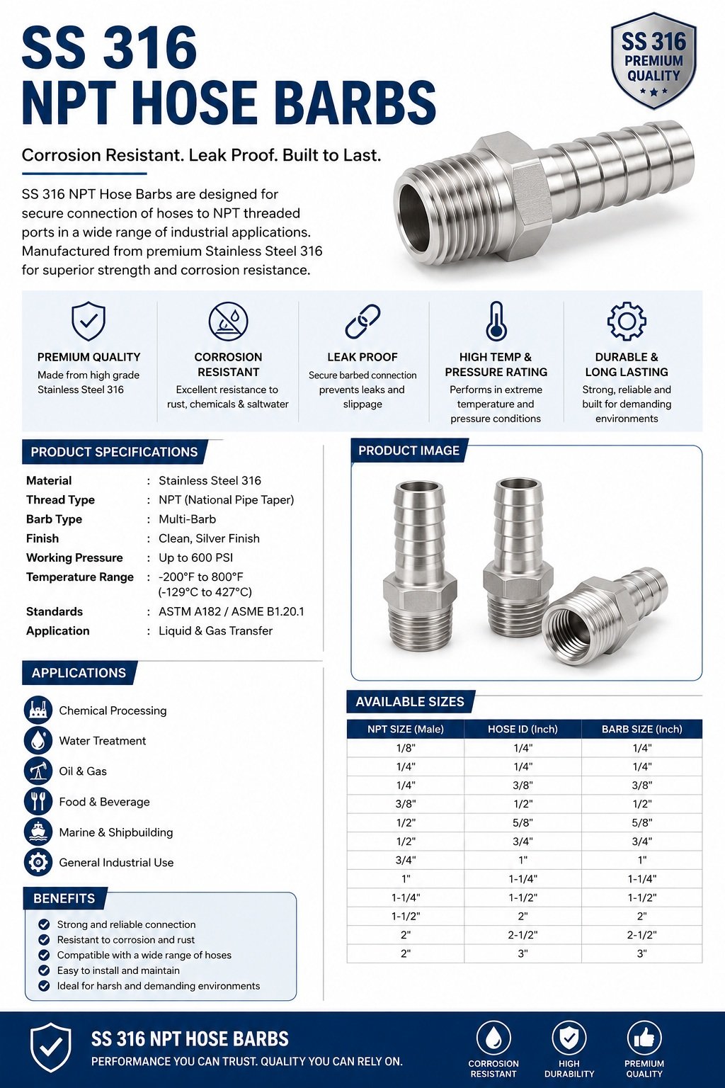
Product Range: Standard Sizes and Configurations
Stainless steel NPT hose barbs are manufactured in a wide range of sizes and configurations to suit different system requirements. The following table summarises the standard product range:
| NPT Thread Size | Hose ID (inches) | Hose ID (mm) | Overall Length (approx.) | Hex Size (AF) | Common Configurations |
|---|---|---|---|---|---|
| 1/8″ NPT | 3/16″ | 5 mm | 38 mm | 11 mm | Straight barb, 90° elbow barb |
| 1/8″ NPT | 1/4″ | 6 mm | 40 mm | 11 mm | Straight barb |
| 1/4″ NPT | 1/4″ | 6 mm | 48 mm | 14 mm | Straight barb, reducing barb |
| 1/4″ NPT | 3/8″ | 10 mm | 52 mm | 14 mm | Straight barb |
| 3/8″ NPT | 1/4″ | 6 mm | 55 mm | 17 mm | Reducing barb |
| 3/8″ NPT | 3/8″ | 10 mm | 55 mm | 17 mm | Straight barb |
| 3/8″ NPT | 1/2″ | 13 mm | 58 mm | 17 mm | Straight barb |
| 1/2″ NPT | 3/8″ | 10 mm | 62 mm | 22 mm | Reducing barb |
| 1/2″ NPT | 1/2″ | 13 mm | 64 mm | 22 mm | Straight barb, elbow, tee |
| 1/2″ NPT | 5/8″ | 16 mm | 68 mm | 22 mm | Straight barb |
| 3/4″ NPT | 1/2″ | 13 mm | 72 mm | 27 mm | Reducing barb |
| 3/4″ NPT | 3/4″ | 19 mm | 76 mm | 27 mm | Straight barb, elbow |
| 1″ NPT | 3/4″ | 19 mm | 88 mm | 36 mm | Reducing barb |
| 1″ NPT | 1″ | 25 mm | 92 mm | 36 mm | Straight barb |
| 1-1/4″ NPT | 1-1/4″ | 32 mm | 108 mm | 46 mm | Straight barb |
| 1-1/2″ NPT | 1-1/2″ | 38 mm | 120 mm | 50 mm | Straight barb |
| 2″ NPT | 2″ | 50 mm | 145 mm | 65 mm | Straight barb |
Pressure Ratings for SS 304 and SS 316 NPT Hose Barbs
Pressure ratings for stainless steel NPT hose barbs depend on thread engagement, wall thickness of the fitting body, and the hose material/reinforcement used. The following ratings are indicative for standard CNC-machined hose barbs with full NPT thread engagement using schedule 80 equivalent wall thickness. Actual safe working pressure is limited by the weakest element in the assembly — in most cases, the hose itself.
| NPT Size | Max Working Pressure — Water/Air (SS 304) | Max Working Pressure — Water/Air (SS 316) | Hydrostatic Test Pressure | Temperature Range |
|---|---|---|---|---|
| 1/8″ | 150 bar (2175 psi) | 150 bar (2175 psi) | 225 bar | −196°C to +400°C |
| 1/4″ | 138 bar (2000 psi) | 138 bar (2000 psi) | 207 bar | −196°C to +400°C |
| 3/8″ | 124 bar (1800 psi) | 124 bar (1800 psi) | 186 bar | −196°C to +400°C |
| 1/2″ | 103 bar (1500 psi) | 103 bar (1500 psi) | 155 bar | −196°C to +400°C |
| 3/4″ | 83 bar (1200 psi) | 83 bar (1200 psi) | 125 bar | −196°C to +400°C |
| 1″ | 69 bar (1000 psi) | 69 bar (1000 psi) | 103 bar | −196°C to +400°C |
| 1-1/4″ | 55 bar (800 psi) | 55 bar (800 psi) | 83 bar | −196°C to +400°C |
| 1-1/2″ | 48 bar (700 psi) | 48 bar (700 psi) | 72 bar | −196°C to +400°C |
| 2″ | 41 bar (600 psi) | 41 bar (600 psi) | 62 bar | −196°C to +400°C |
Disclaimer: These are indicative values for the fitting body only. Always derate for elevated temperature, pulsating flow, and hose assembly type. Consult manufacturer datasheets for certified pressure ratings.
Corrosion Resistance: SS 304 vs SS 316 — When to Use Which Grade
The choice between SS 304 and SS 316 is primarily driven by the corrosivity of the fluid media and the external environment. The 2–3% molybdenum content in SS 316 raises its Pitting Resistance Equivalent Number (PREN = %Cr + 3.3×%Mo + 16×%N) from approximately 18–20 for SS 304 to approximately 24–26 for SS 316 — a substantial improvement in resistance to localised chloride-induced corrosion.
| Application / Media | Recommended Grade | Reason |
|---|---|---|
| Potable water, deionised water | SS 304 | Low chloride; SS 304 fully adequate and cost-effective |
| Food and beverage (neutral pH) | SS 304 or SS 316 | SS 304 per FDA 21 CFR; SS 316 for CIP/SIP cleaning with chlorinated solutions |
| Pharmaceutical (WFI, Clean Steam) | SS 316L | Low carbon 316L minimises sensitisation risk; MOlybdenum assists CIP resistance |
| Seawater / marine | SS 316 | Chloride concentration requires Mo for pitting resistance |
| Chemical plant — acids (dilute) | SS 316 | Better resistance to sulphuric and phosphoric acids at moderate concentrations |
| Chemical plant — concentrated oxidising acids | Hastelloy / PTFE lined (not SS) | Nitric acid >65% attacks SS 316; consult corrosion table |
| Compressed air / pneumatics | SS 304 | Non-corrosive; SS 304 fully satisfactory |
| Hydraulic oil / mineral oil | SS 304 | Oils are not corrosive to austenitic stainless; SS 304 adequate |
| Coastal / offshore outdoor service | SS 316 | Airborne chloride deposit demands Mo-bearing grade |
| Cryogenic service (LN2, LNG) | SS 304 or SS 316 | Both retain toughness to −196°C; SS 316 preferred for corrosive cryogens |
| Steam lines | SS 316 | Condensate with chloride impurities; Mo protective |
Stainless Steel vs Brass vs Plastic Hose Barbs: Complete Technical Comparison
| Property | SS 304 / SS 316 | Brass (C36000 / C38500) | Nylon / Polypropylene |
|---|---|---|---|
| Tensile Strength | 515 MPa min | 340–415 MPa (annealed) | 50–80 MPa |
| Max Working Pressure | 41–150 bar (size dependent) | 35–110 bar | 7–12 bar |
| Max Temperature | 400°C (continuous) | 177°C max (dezincification above 80°C) | 60–120°C (grade dependent) |
| Min Temperature | −196°C (cryogenic) | −55°C | −20°C to −40°C |
| Chloride Resistance (SS 316) | Excellent (PREN 24–26) | Poor — dezincification in chloride media | Excellent |
| Food/Pharma Compliance | FDA 21 CFR, EU 10/2011 (SS 316) | Limited — lead content concern | Grade-dependent FDA compliance |
| UV / Outdoor Resistance | Excellent | Patinas (acceptable) | Poor (UV degradation without stabiliser) |
| Hygienic Cleanability (CIP/SIP) | Excellent — smooth, non-porous | Good | Limited above 80°C |
| Corrosion without Surface Treatment | Fully corrosion resistant (passive layer) | Requires environment control | Fully resistant to most chemicals |
| Cost (relative) | High | Medium | Low |
| Weight | 7.93–7.98 g/cm³ | 8.5 g/cm³ | 1.0–1.3 g/cm³ |
| Service Life (typical) | 20–30+ years | 5–15 years | 3–10 years |
Installation Guide: How to Install Stainless Steel NPT Hose Barbs Correctly
Correct installation is critical to achieving leak-free, long-service-life connections. The following procedure applies to standard NPT hose barbs with flexible hose and a clamp.
Tools and Materials Required
- Open-end or adjustable wrench sized to the hex body
- PTFE thread tape (white, 12–25 mm wide, density 0.2–0.3 g/cm³) or anaerobic thread sealant (Loctite 567 or equivalent) for high-pressure hydraulic service
- Stainless steel hose clamps (worm-drive or T-bolt) — SS 304 or SS 316 to match fitting grade
- Torque wrench for critical applications
- Hose lubricant (silicone grease or soapy water — never petroleum-based if hose is EPDM or NBR)
Installation Steps
- Inspect fitting: Confirm grade marking, check thread for damage, verify barb profile is intact.
- Apply thread sealant: Wrap PTFE tape 2–3 turns clockwise (direction of thread tightening) starting from the second thread. For high-pressure or gas service, use 3–4 wraps. Alternatively apply anaerobic sealant to the first 4–5 threads.
- Thread in by hand: Engage the NPT male thread into the female port 2–3 turns by hand. Resistance indicates the taper is engaging.
- Wrench tighten: Apply wrench to the hex body. Standard NPT assembly torque guideline — 1/8″: 7–11 N·m; 1/4″: 10–16 N·m; 3/8″: 14–24 N·m; 1/2″: 20–34 N·m; 3/4″: 28–48 N·m; 1″: 40–68 N·m. Do NOT use the barb shank or hose assembly as the torque reaction point — this will stress the barb profile. For final orientation alignment, additional turns are acceptable up to maximum engagement of the L2 gauge length.
- Prepare hose: Cut hose square with a sharp blade — a rough cut causes leakage past the barb. If the hose is hard to push on, warm it briefly in hot water (60–70°C for 30 seconds).
- Lubricate and push hose onto barb: Apply silicone grease or soapy water to the barb shank. Push hose firmly onto the barb until the hose end contacts the hex body step. Ensure the hose is fully seated — a partially seated hose will leak under pressure and can blow off.
- Apply hose clamp: Position the clamp band over the hose at the first barb ridge position (within 10 mm of the hex step). Tighten the clamp to the hose manufacturer’s recommended torque — typically 2–4 N·m for worm-drive clamps. For high-pressure or pulsating service, use two clamps at 180° offset.
- Pressure test: Test the assembled connection hydrostatically at 1.5× maximum working pressure for 5 minutes minimum before returning to service.
Applications: Industries and Systems Using SS NPT Hose Barbs
| Industry | Application | Grade Used | Key Requirement |
|---|---|---|---|
| Chemical Processing | Chemical dosing lines, reagent transfer, acid/base distribution | SS 316 | Corrosion resistance; compatibility with aggressive media |
| Food & Beverage | CIP (Clean-In-Place) circuits, product transfer lines, brewing, dairy | SS 304 / SS 316L | FDA compliance; smooth bore for cleanability; no dead-legs |
| Pharmaceutical | WFI water circuits, clean steam lines, buffer transfer | SS 316L | Low carbon; Ra ≤ 0.8 µm bore; full traceability with MTC |
| Marine & Offshore | Seawater cooling, bilge pumping, deck wash, exhaust cooling | SS 316 | Chloride pitting resistance; saltwater immersion tolerance |
| Oil & Gas | Instrument impulse lines, sample probe tubing, chemical injection | SS 316 | H2S tolerance; high-pressure rating; corrosion under insulation (CUI) resistance |
| Water Treatment | Dosing pump connections, filter housings, RO system piping | SS 304 / SS 316 | Potable water approval; chemical dosing compatibility |
| HVAC & Refrigeration | Chiller water circuits, glycol loops, condensate drains | SS 304 | Corrosion resistance to glycol/water mixtures |
| Instrumentation | Differential pressure transmitter impulse lines, analyser sample systems | SS 316 | Small bore (1/8″–1/4″ NPT); leak-tight; vibration resistance |
| Brewery & Winery | Product and CIP hose connections, CO2 lines | SS 316L | Hygienic; resistance to organic acids (lactic, acetic, citric) |
| Semiconductor / Microelectronics | Ultra-pure water circuits, chemical delivery systems | SS 316L (electropolished) | Ra ≤ 0.4 µm; no particle generation; electropolished finish |
Applicable Standards and Certifications
| Standard / Certification | Scope | Relevance to SS NPT Hose Barbs |
|---|---|---|
| ASME B1.20.1 | NPT thread dimensions, tolerances, gaging | Mandatory thread standard for all NPT hose barbs supplied to USA and international markets |
| ASTM A276 / A479 | Stainless steel bar stock specification | Material certification standard for CNC-machined bar stock input material |
| ASTM A967 / AMS 2700 | Passivation of stainless steel | Defines acceptable passivation process and testing requirements |
| ISO 9001:2015 | Quality management system | Manufacturing quality system certification for supplier qualification |
| FDA 21 CFR 177 / EU 10/2011 | Food contact materials | Compliance for food, beverage, and pharmaceutical hose systems |
| NACE MR0175 / ISO 15156 | Sour service (H2S) materials qualification | Relevant for oil & gas applications with H2S; SS 316 annealed meets requirements |
| EN 10204 3.1 / 3.2 | Material test certificates | 3.1 MTC (manufacturer-certified) or 3.2 (third-party witnessed) for critical service |
| PED 2014/68/EU | European Pressure Equipment Directive | Required for pressure-bearing assemblies used within EU member states |
| ATEX / IECEx | Explosive atmosphere compliance | Stainless steel fittings in ATEX zones require non-sparking certification for some configurations |
Common Failure Modes and Troubleshooting
| Failure Mode | Root Cause | Prevention / Remedy |
|---|---|---|
| Thread leak at NPT joint | Insufficient PTFE tape; over-tightening causing galling; damaged thread | Apply 3 wraps minimum PTFE tape; use anti-galling lubricant (Molykote or Nickel paste) for SS-to-SS assembly; replace damaged fittings |
| Hose blow-off under pressure | Hose not fully seated on barb; clamp over wrong position; clamp torque too low; wrong hose ID — insufficient interference | Verify full hose seating to hex step; position clamp at first barb ridge; retighten to specified torque; verify hose ID vs barb OD interference specification |
| Pitting corrosion on fitting body | Chloride media with SS 304; inadequate passivation; crevice under clamp | Upgrade to SS 316 for chloride service; ensure passivation per ASTM A967; use SS 316 clamp; drain and dry system when not in use |
| Galling (thread seizure) during installation | Metal-to-metal contact between SS male and SS female threads at high torque | Apply anti-galling compound (Molykote G-1000, Jet-Lube SS-30, or PTFE tape); avoid excessive torque; ensure threads are free of debris |
| Stress corrosion cracking (SCC) | Sensitised SS in chloride media at elevated temperature (>60°C) | Use 316L (low carbon) grade; ensure solution anneal after any heat input; avoid sensitisation-prone environments or upgrade to duplex SS |
| Hose cracking at barb entry | Excessive interference; hose over-hardened by UV or age; incorrect hose material for temperature | Reduce interference specification; replace aged hose; select correct hose compound for temperature range |
Why Source Stainless Steel NPT Hose Barbs from India?
India has emerged as a globally recognized manufacturing hub for precision stainless steel fittings, serving markets in the USA, Europe, Middle East, Southeast Asia, and Australia. Indian manufacturers offer a unique combination of technical capability, material traceability, competitive pricing, and export experience that makes them preferred suppliers to EPC contractors, distributors, and OEMs worldwide.
| Advantage | Details |
|---|---|
| Raw Material Availability | Direct access to SAIL, TISCO, and Jindal stainless bar stock; imported European and Japanese bar available for critical service applications |
| CNC Manufacturing Capability | Modern multi-axis CNC turning centres; Swiss-type lathes for small-bore precision; CMM inspection; full thread gauging per ASME B1.20.1 |
| Quality Certifications | ISO 9001:2015; PED CE marking; NABL-accredited lab testing; third-party inspection by TUV, Bureau Veritas, SGS, Intertek available |
| Competitive Pricing | 20–40% cost advantage over comparable European or US-manufactured fittings for equivalent material and dimensional quality |
| Full Documentation | EN 10204 3.1 MTCs; dimensional inspection reports; PMI test reports; passivation certificates; REACH/RoHS compliance documentation |
| Customisation | Non-standard barb diameters, special hex sizes, custom lengths, electropolished bore, special markings — all available to drawing |
| Lead Times | Standard sizes ex-stock or 2–4 weeks; custom / special sizes 4–8 weeks; expedited available |
| Export Packaging | Moisture-barrier poly bags with desiccant; individual poly bags; bulk or retail pack; carton markings per buyer specification |
How to Specify Stainless Steel NPT Hose Barbs: Ordering Information
To ensure correct supply, the following information should be provided when ordering:
- Material Grade: SS 304 or SS 316 (specify L-grade if low carbon is required)
- NPT Thread Size: e.g., 1/2″ NPT male
- Hose Barb Size (ID): e.g., 1/2″ hose ID (13 mm)
- Configuration: Straight / 90° elbow / 45° elbow / Tee / Y-piece
- End Connection: NPT male or NPT female (socket-type female NPT barbs are also available)
- Surface Finish: Standard passivated / electropolished / bright annealed
- Documentation: EN 10204 3.1 MTC / 3.2 / PMI test / passivation certificate
- Quantity and Delivery: Required quantity; delivery port (FOB, CIF, DAP)
- Applicable Standards: ASME B1.20.1 for thread; ASTM A276/A479 for material
Frequently Asked Questions (FAQ)
What is the difference between NPT and BSPT threads on hose barbs?
NPT (National Pipe Taper, ASME B1.20.1) and BSPT (British Standard Pipe Taper, BS 21 / ISO 7-1) are both tapered pipe threads but are NOT interchangeable. They share the same 1/16″ per inch taper angle but differ in thread form angle (60° for NPT vs 55° for BSPT/Whitworth), pitch, and pitch diameter. Mixing NPT and BSPT threads produces a leak-prone assembly and may cause cross-threading. Always verify the female thread standard before ordering hose barbs.
Can stainless steel NPT hose barbs be used with PTFE hose?
Yes. Smooth-bore PTFE hose can be assembled onto stainless steel barbs with an outer stainless-steel crimp ferrule or socket clamp, since PTFE does not stretch over barbs like rubber hose. The PTFE hose-barb combination requires proper crimping tooling and validated crimp specifications — a worm-drive clamp alone is insufficient for PTFE hose assemblies.
What hose clamp grade should I use with SS 316 hose barbs?
Always use SS 316 stainless steel hose clamps (band and housing both SS 316) with SS 316 hose barbs in corrosive or marine environments. Using SS 304 or zinc-plated steel clamps will create galvanic compatibility issues and the clamp will corrode preferentially, compromising the assembly before the fitting itself.
Is PTFE tape sufficient for NPT hydraulic service?
For working pressures above 70 bar, or for hydraulic oil service, many engineers prefer anaerobic thread sealant (Loctite 567 or equivalent stainless-compatible grade) in addition to or instead of PTFE tape. Anaerobic sealants cure in the absence of air within the thread interface, filling all micro-gaps and providing vibration-resistant sealing superior to PTFE tape alone.
Call to Action: Request a Quote for Stainless Steel NPT Hose Barbs from India
Get a Competitive Quote — SS 304 & SS 316 NPT Hose Barbs, Manufactured in India
We manufacture and export precision CNC-machined stainless steel hose barbs with NPT threads in SS 304 and SS 316 to customers in the USA, Europe, Middle East, Southeast Asia, and Australia. Our fittings are manufactured to ASME B1.20.1 thread standards, fully passivated per ASTM A967, and supplied with EN 10204 3.1 Mill Test Certificates.
- Full range: 1/8″ NPT to 2″ NPT — straight, elbow, tee, reducing configurations
- Grades: SS 304, SS 316, SS 304L, SS 316L — electropolished available
- Quality: ISO 9001:2015 certified; third-party inspection (TUV, BV, SGS, Intertek) arranged on request
- Lead times: Ex-stock for standard sizes; 3–6 weeks for custom specifications
- Minimum order: Low MOQ for samples; competitive pricing for volume orders
Contact us today with your size, grade, quantity, and delivery requirements — we will respond within 24 hours with a detailed technical quotation.